

1. Tension Clamp Detection
1.1 Industry Pain Points
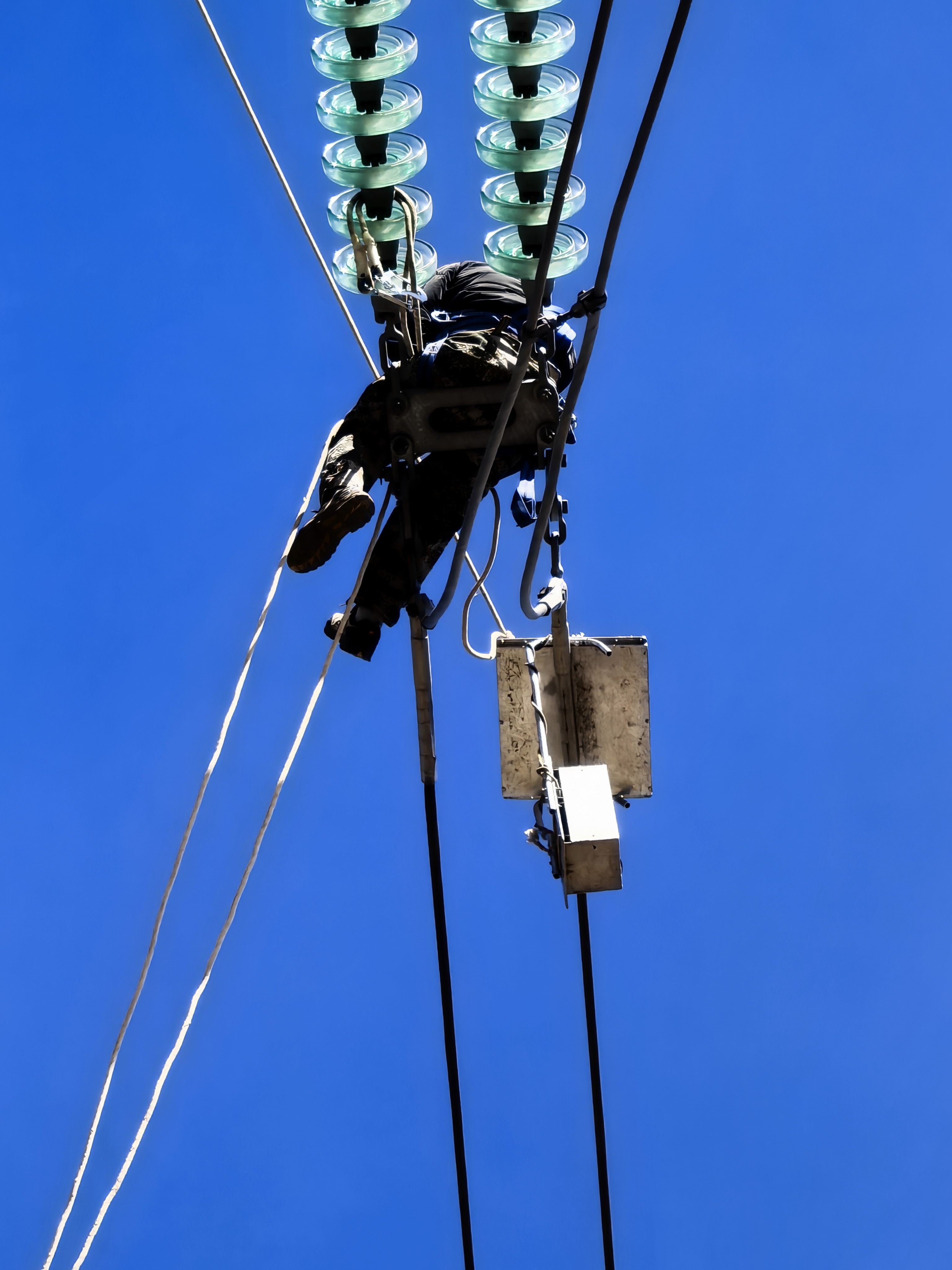
In the power transmission system, tension clamps are important components that connect fittings and wires, and their internal health directly determines the mechanical safety of the line; The wire clamp is exposed to the natural environment for a long time and is susceptible to hidden dangers such as corrosion, fracture, loosening, and detachment due to external factors. Once there are hidden defects inside the wire clamp and hidden dangers outside, it is highly prone to wire breakage, flashover, and line tripping, ultimately leading to safety accidents such as fire, electric shock, and large-scale power outages, seriously affecting the smooth operation of power transmission.
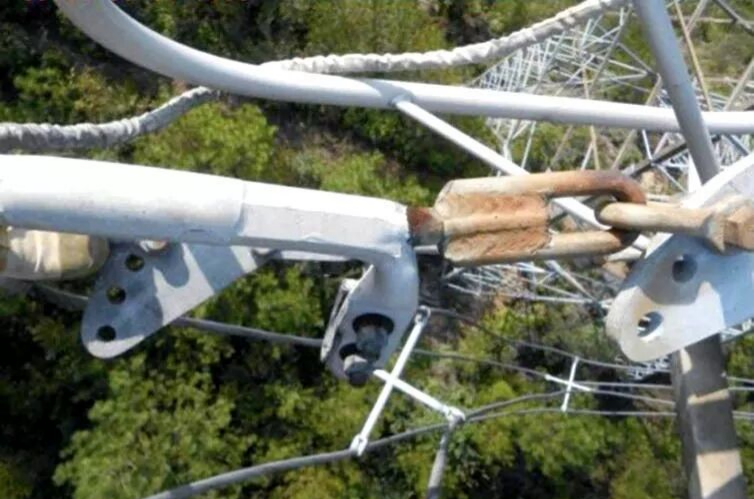
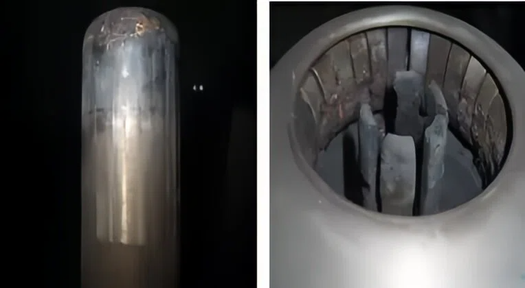
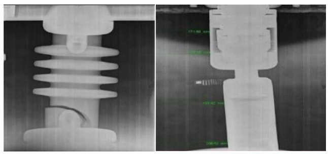
Bending deformation of a 550kV transmission line clamp
Especially in the "Three Crosses" area, the cost of post repair and power outage losses is tens of times higher than the initial testing costs. It is precisely because of the importance of wire clamps that the inspection of wire clamps is particularly important. Currently, regular inspection of wire clamps has become an important part of power operation and maintenance. However, due to the precise and complex structure of components, traditional manual inspection still has many drawbacks and has a significant impact.
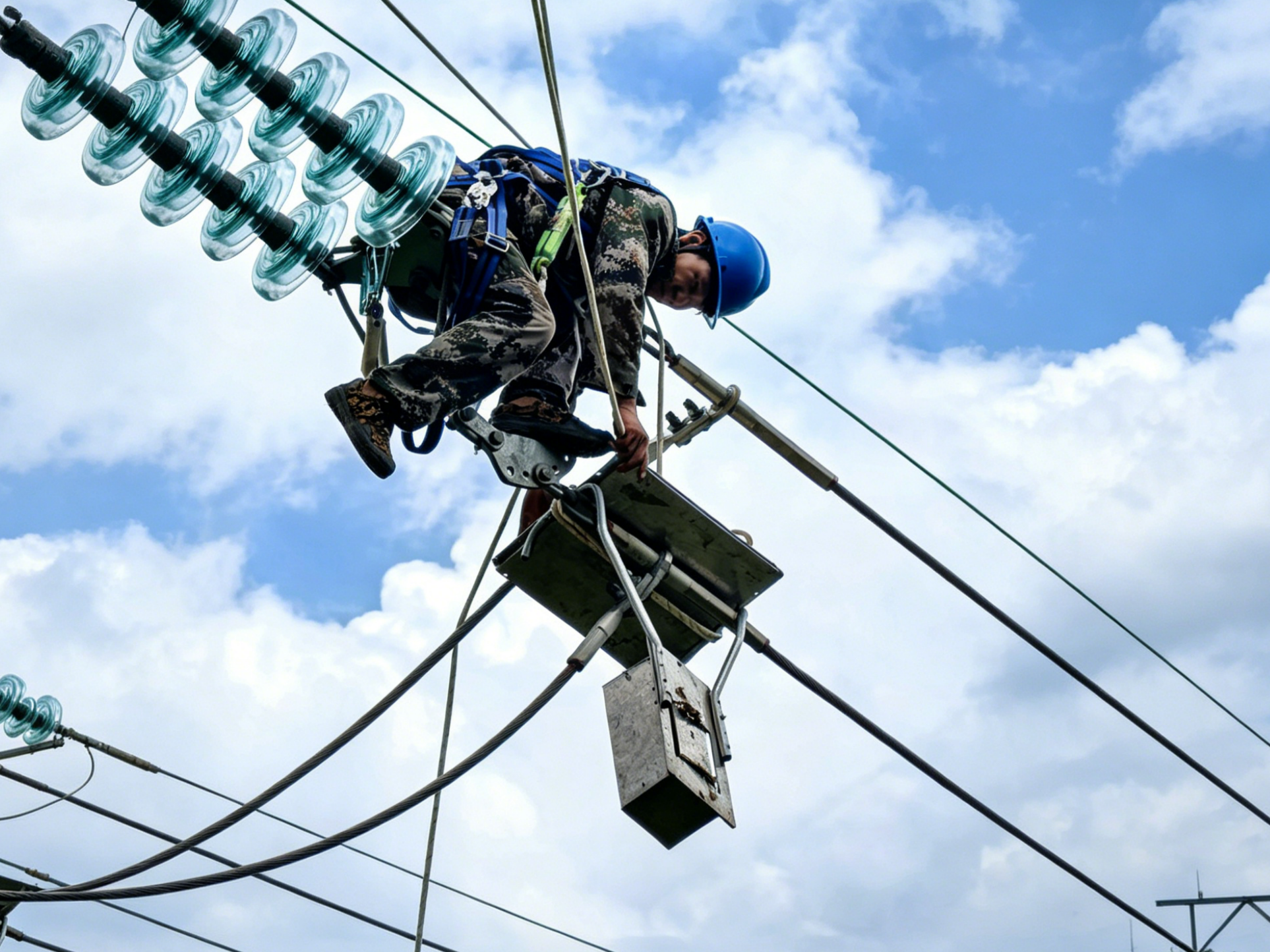
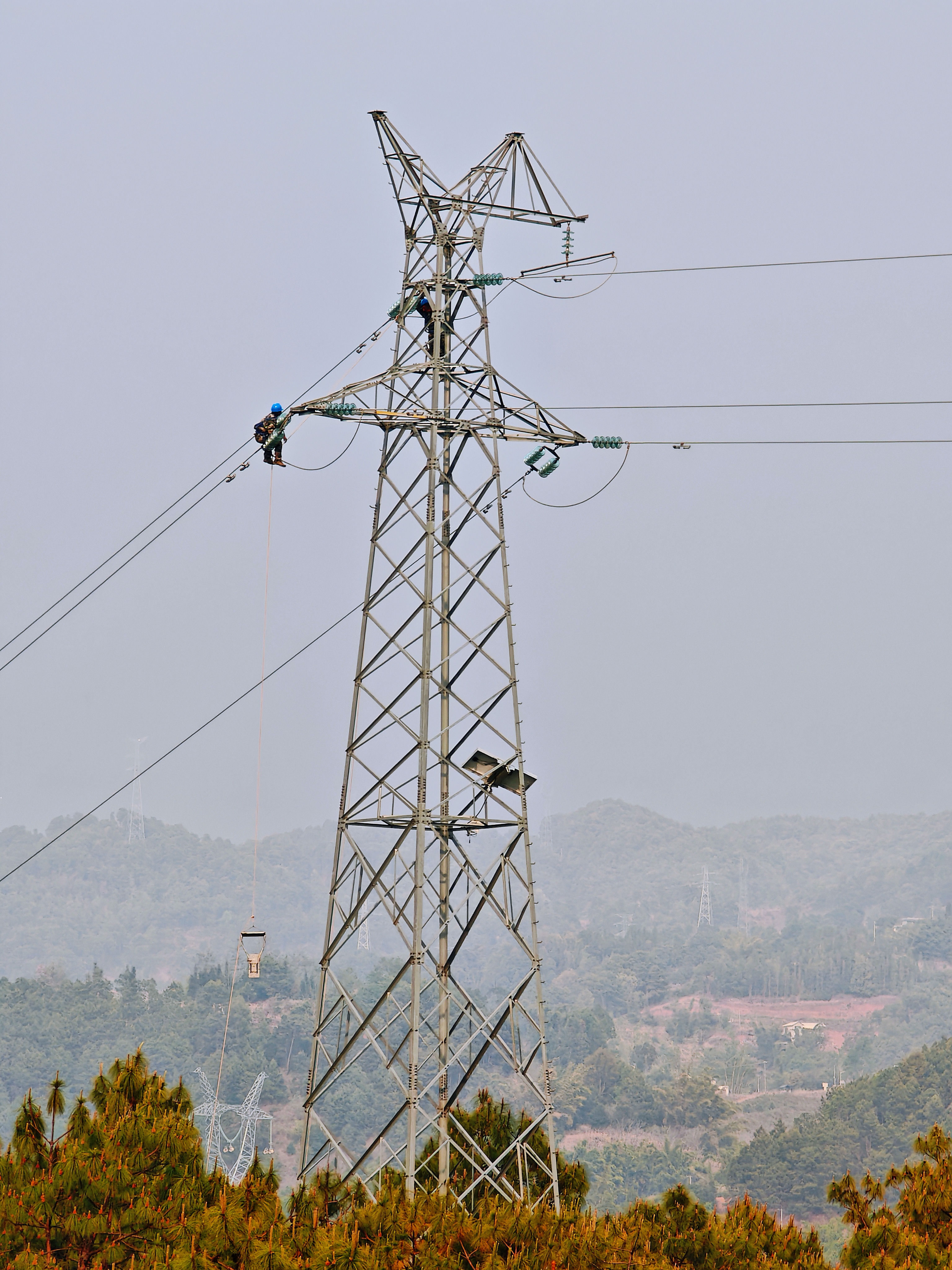
The drawbacks of traditional manual wire clamp detection include low efficiency, slow emergency response capability, incomplete coverage, time-consuming and laborious, and limited daily inspection coverage; High safety risk, risk of electric shock and falling, and susceptible to external factors such as weather and terrain interference; Inaccurate investigation, visual observation, easy to overlook problems and hidden dangers, manual data recording, difficult data retention and statistics; High cost and large manpower shortage. High labor costs, long impact time, and few professional testing personnel.
1.2 Ana X-ray Solution
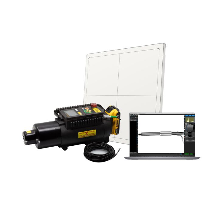
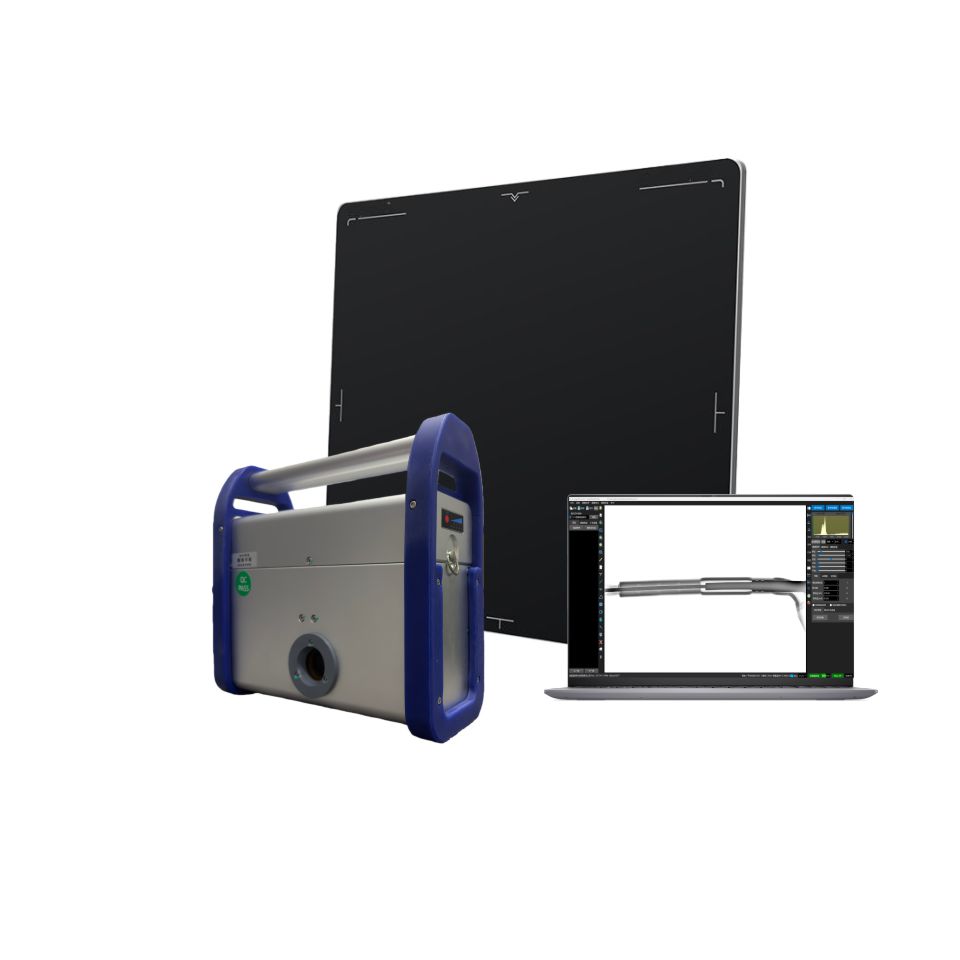
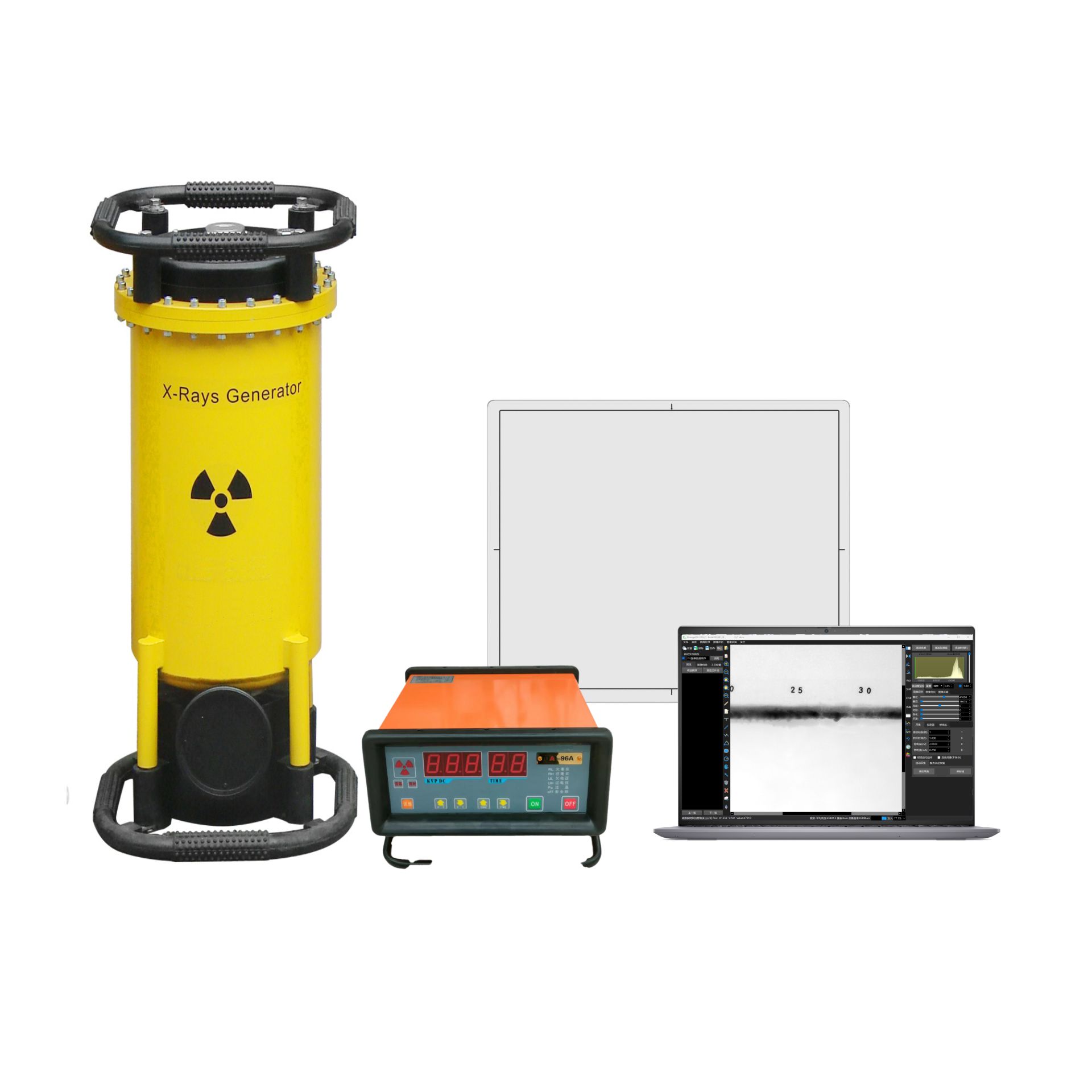
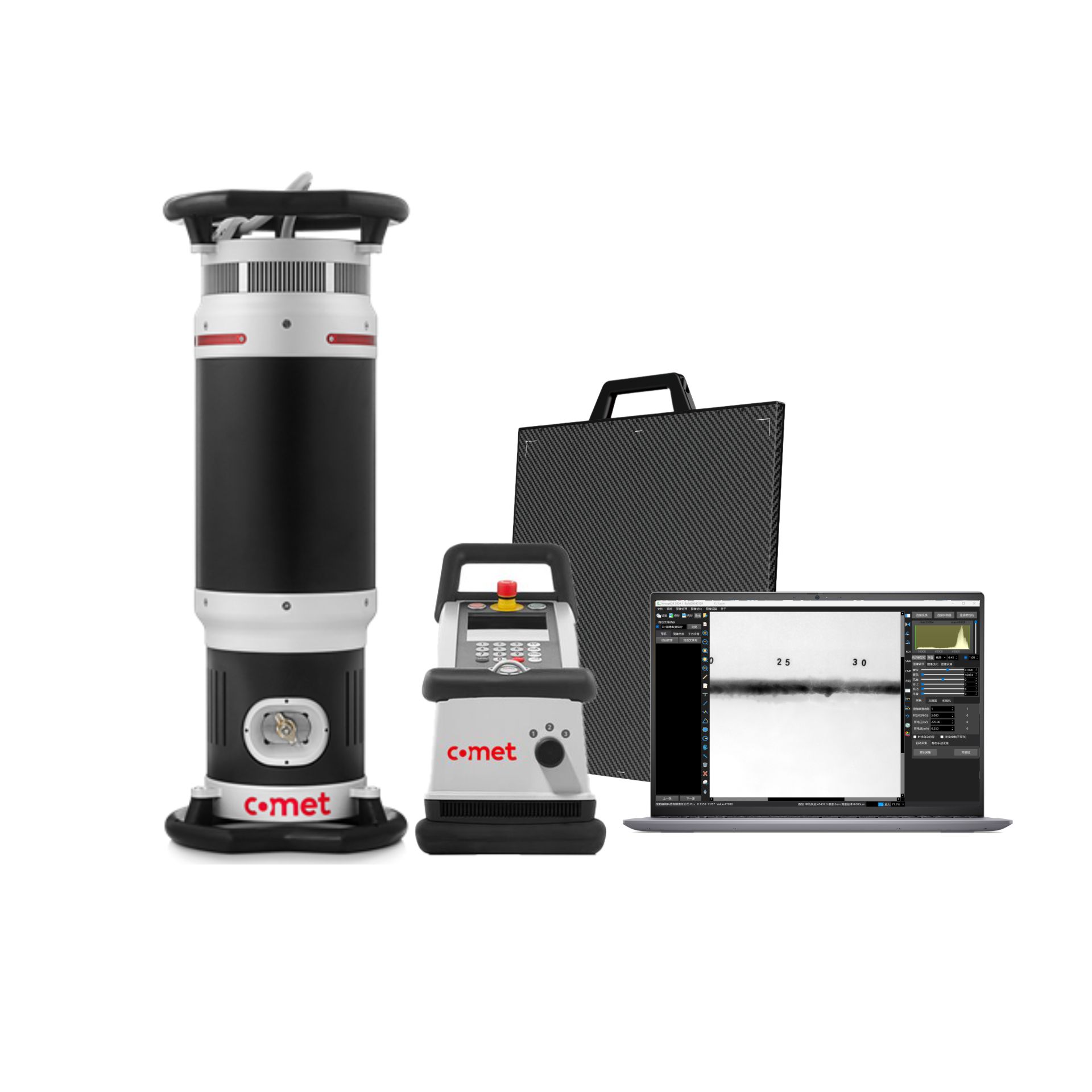
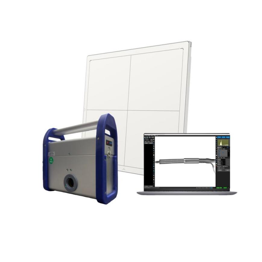
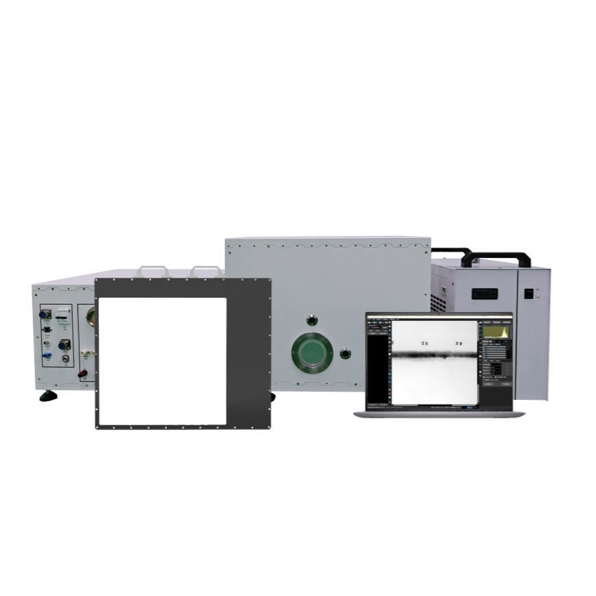
Defects are internal and cannot be detected through visual inspection. Therefore, using X-ray technology to detect and explore internal hidden dangers is an essential part of ensuring the safe and reliable operation of the power grid. Ona Technology's X-ray power detection solution provides a portable X-ray imaging system with DR digital imaging and intelligent analysis software as the core, covering key equipment in the entire power transmission and transformation scene, providing visual, precise, and intelligent technical support for the safe operation of the power grid.

Two major plans
|
|
1.2.1 Manual Outage Operation
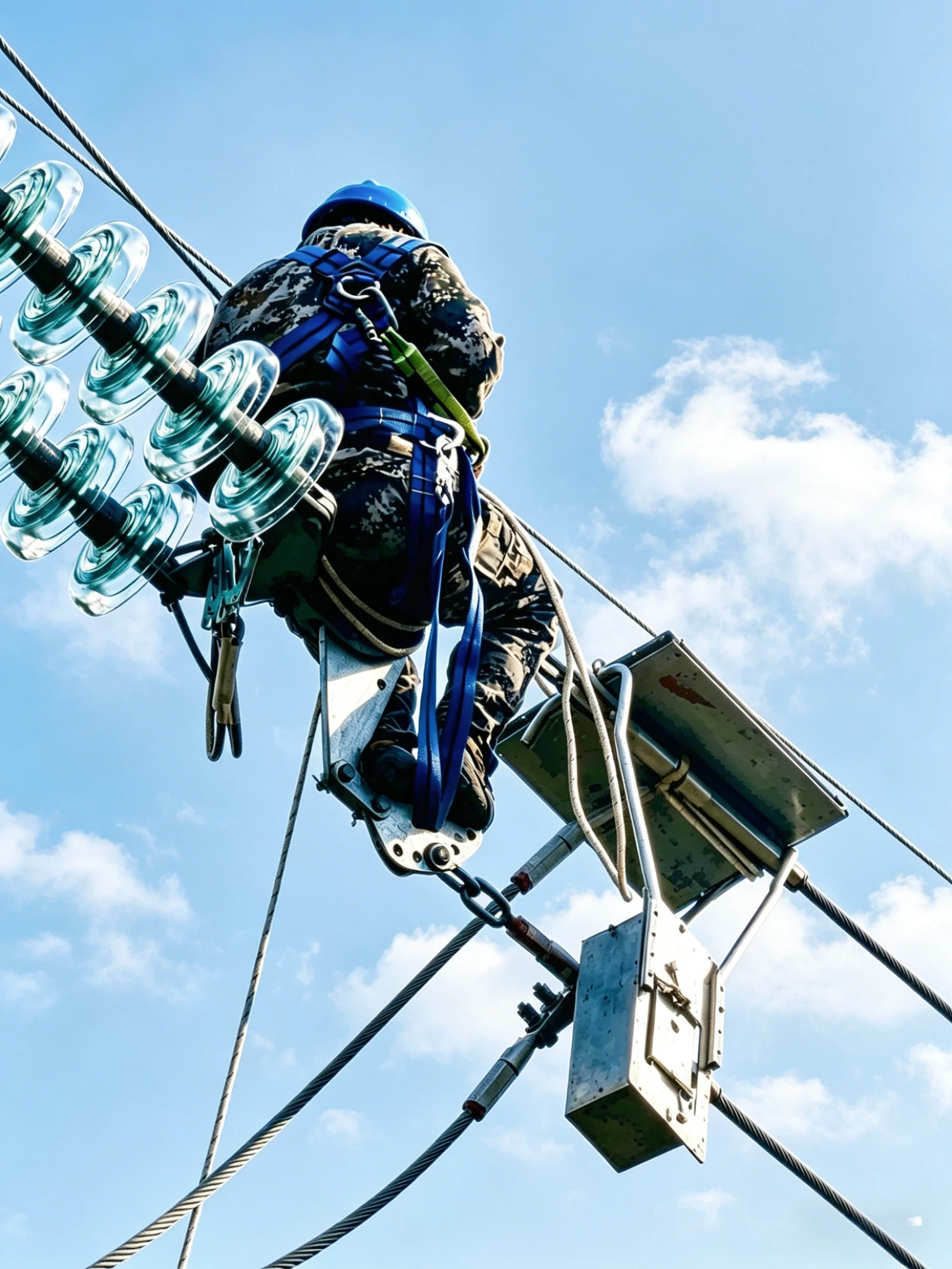
| Advantages: Non-destructive testing: no disassembly, damage, and fluoroscopic inspection of internal defects Efficient and fast: short image acquisition and processing time, real-time imaging Precise and reliable: Accurately locate defects and provide visual basis for fault diagnosis Scenario adaptation: portable battery power supply, adaptable to various complex operating environments |
Disadvantages: Low efficiency: lifting equipment and operation on and off the tower are required, which is time-consuming and labor-intensive Wide influence: operation with power cut is required, which disturbs normal power utilization of the society Potential safety hazard: high falling risk and radiation hazard, threatening the safety of operators Limited coverage: it is difficult to fully cover complex working conditions such as multi-split conductor |
|
1.2.2 UAV Live Working
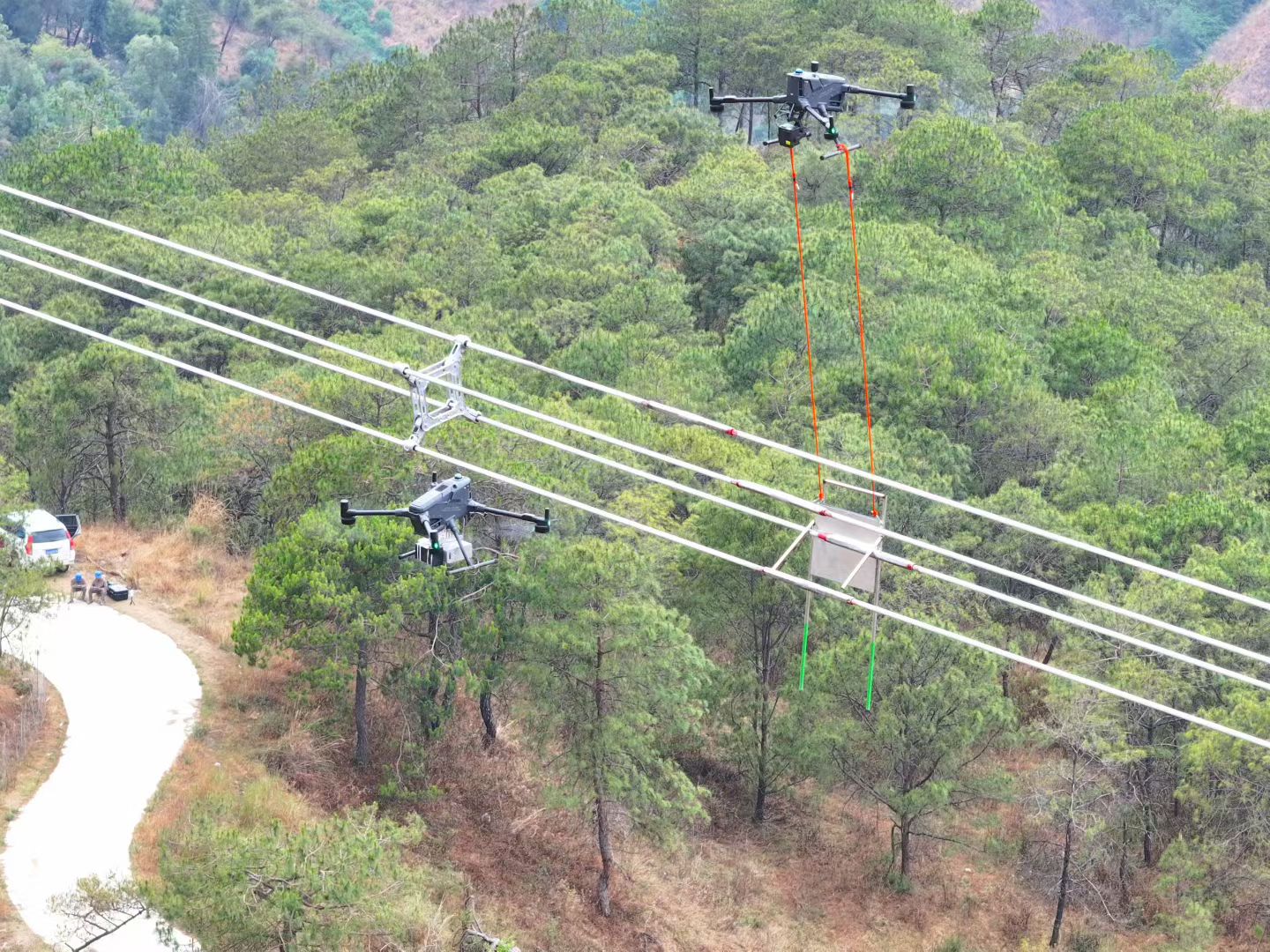
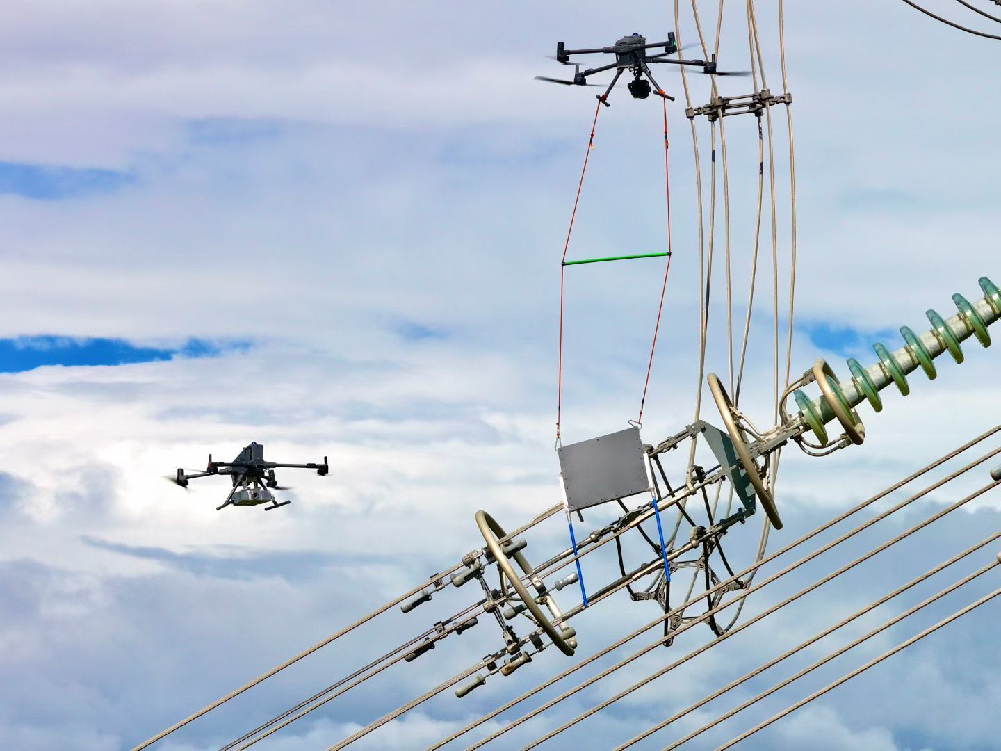
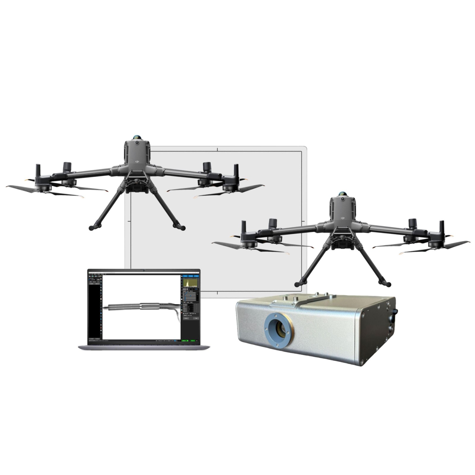
The drone is equipped with a portable X-ray detection device and flies to the target location to perform flaw detection on the transmission line clamp. The X-ray source is activated, and the software displays the imaging results in real time. Based on the standard, it determines whether there are hidden defects such as improper crimping, cracks, eccentricity, wire strand damage, broken strands, steel pipe slip or deformation in the tension clamp, and takes timely measures to solve them.
| Advantages: High detection efficiency: high image quality, intuitive and visible internal blind spot defects; Accurate and efficient, with no missed detection of small defects, real-time imaging, and significantly reduced detection time. Non destructive testing: no disassembly, no damage, no shutdown (or short-term power outage). Safe and convenient: The drone is used for live testing, avoiding high-altitude operations and X-ray radiation, effectively ensuring the life and health of workers. |
Advantages: Powerful image processing capabilities: integrated software and hardware, self-developed software+mature equipment, one-stop delivery, reducing system integration difficulty. On site adaptation: battery powered, portable design, suitable for complex environments such as substations, power lines, and mountainous areas. Preventive maintenance: Pre check for defects in power equipment, improve predictive ability, and reduce the chain reaction and economic losses caused by power failures. | 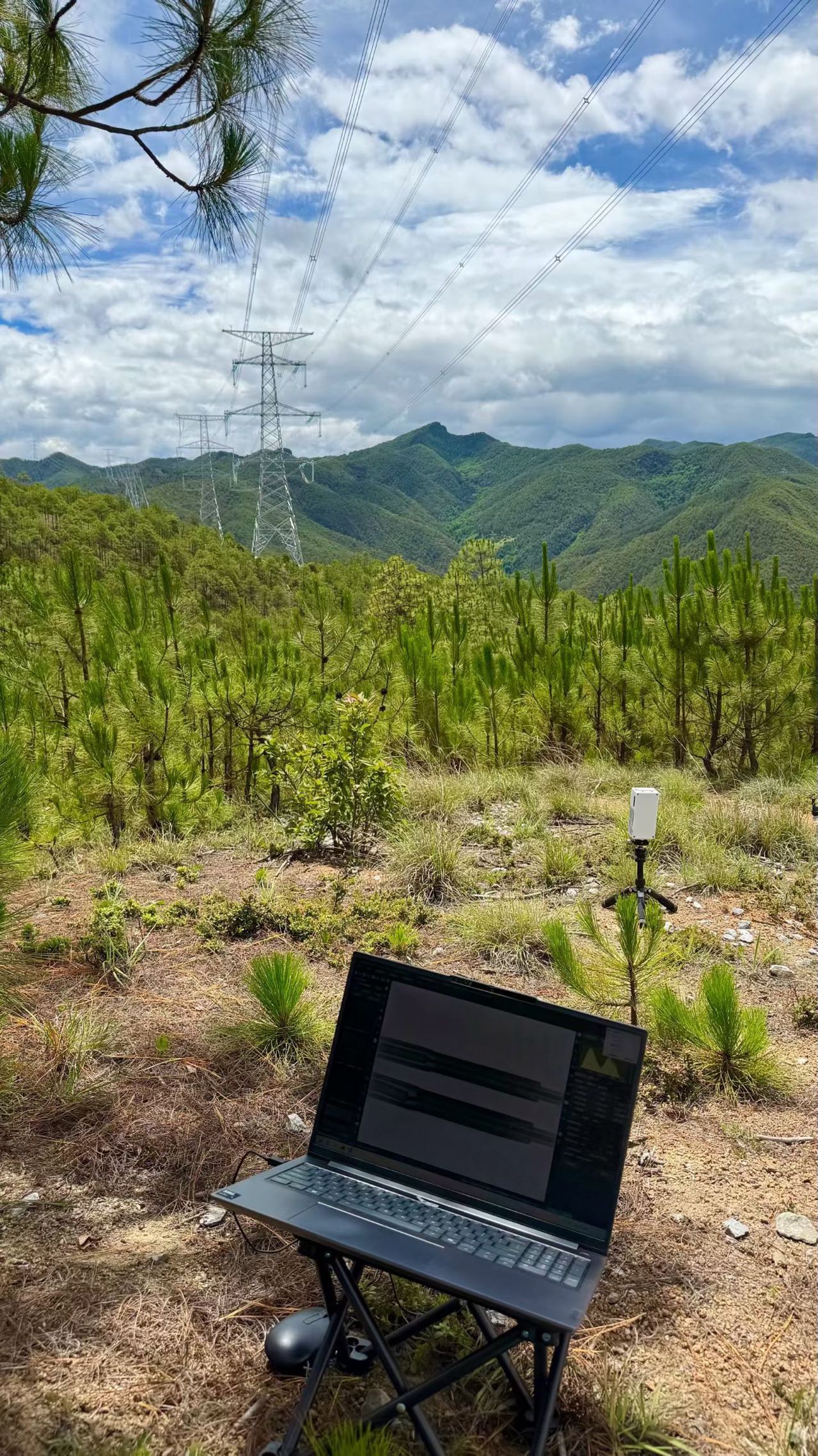 |
Recommended solution for Ana clamp detection
|
|
|
1.3 Effect Diagram of Tension Clamp Detection
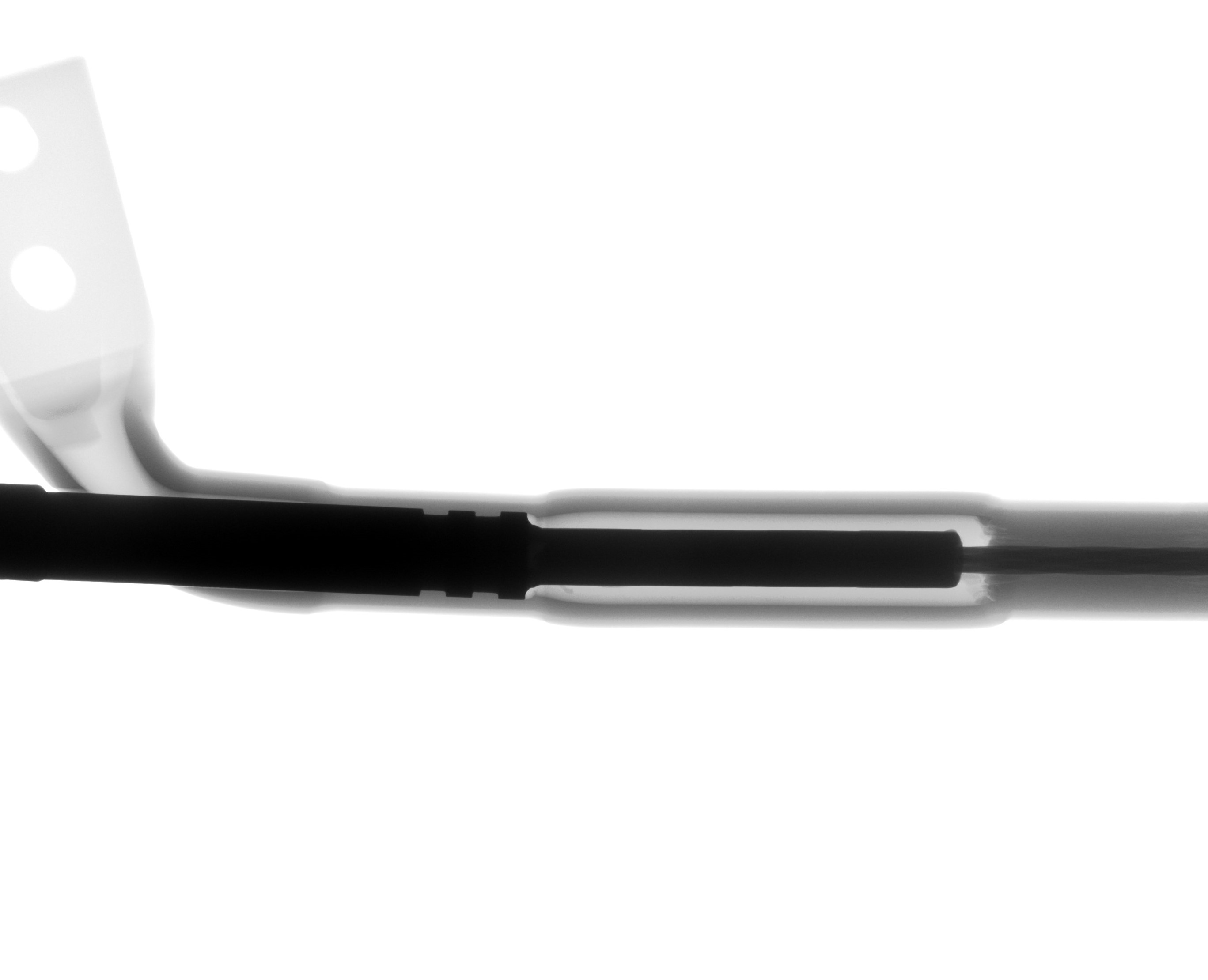
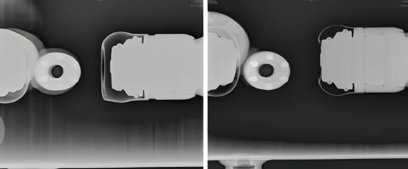
Strain clamp not enhanced |
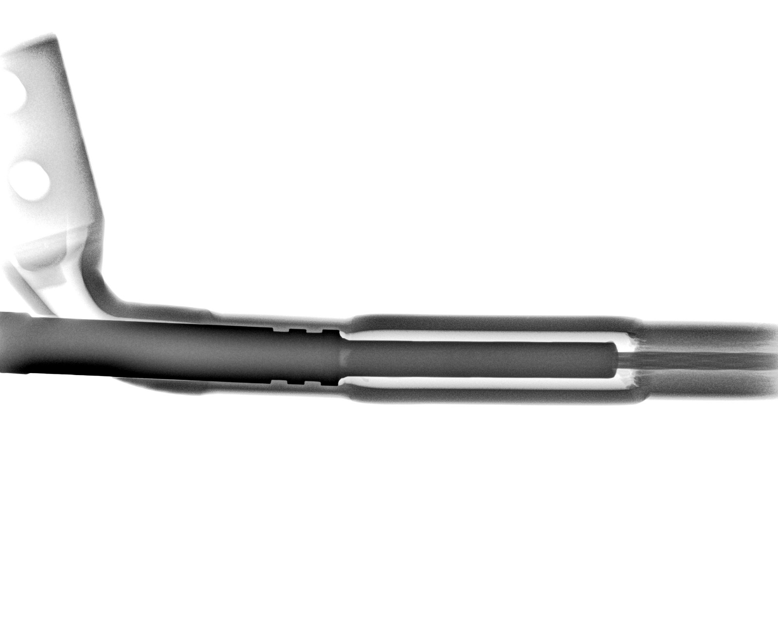
One-key enhancement of strain clamp software (once) |
2.GIS Detection
2.1 GIS Equipment Detection Dilemma
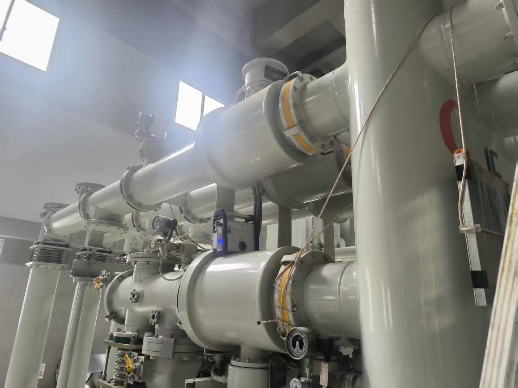
GIS is a key equipment for power grid transmission hub and load hub, and urban power grid and ultra-high voltage power grid are almost inseparable from it. GIS equipment is a metal sealed structure that is not affected by external environmental factors. However, due to the inherent detection difficulties caused by this structure, defects such as internal cracks and loose components cannot be visually inspected, which can easily lead to serious malfunctions.
GIS internal insulator cracking and installation misalignment can cause internal flashover, phase to phase short circuit, etc. In severe cases, tank explosion and gas explosion can directly cause the entire station to trip. Poor crimping of GIS joints and loose contact of conductors lead to long-term overheating and erosion, gradually burning and melting of conductors and insulators, and ultimately developing into internal short circuits and busbar burnout.
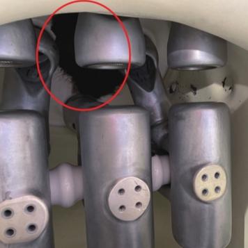
Explosion of insulator and disassembly of gas chamber |
Contact is burned |
Through GIS equipment detection, problems and defects can be found, electrical and mechanical properties of the line can be evaluated, and timely maintenance and repair can be carried out to reduce power outage caused by line faults and ensure stable operation of the line. However, the traditional infrared imaging can only monitor the abnormal temperature, and the partial discharge detection cannot realize the structure visualization, with obvious limitation.
Limitations of traditional GIS equipment detection technology
Low precision in defect localization | Unable to visually display the internal structure of GIS equipment, making it difficult to accurately determine the specific location, size, and form of defects. In strong electromagnetic environments such as high-voltage substations, electromagnetic radiation and conducted interference cause signal distortion and high misjudgment rates |
Low precision in defect localization | Dismantling the equipment casing is time-consuming and labor-intensive, and can easily damage the sealing of the equipment, affecting its insulation performance |
Passive detection mode | The regular maintenance mode relies on a fixed cycle and cannot dynamically track the trend of defect degradation, often leading to "small defects dragging into big failures" |
Incomplete coverage of detection issues | Ultra high frequency and ultrasonic discharge cannot provide early warning for discharge caused by sudden falling foreign objects, and are ineffective for defects such as loose screws |
2.2 Recommended Solution for Ana GIS Detection
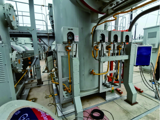
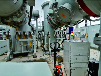
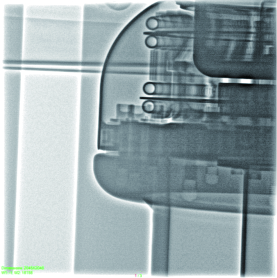
The equipment has high penetration power, and internal blind spot defects are visually visible without disassembling the equipment, accurately locating potential defects, preventing the expansion of faults, and verifying the quality of maintenance. At the same time, predict potential safety hazards in the operation of GIS equipment, record and manage various defects, proactively control equipment operation risks, and improve equipment operation reliability.
Recommended solution for Ana GIS detection
|
|
|
|
2.3 GIS Detection Category
| Assembly abnormality Are screws/bolts and other components loose, broken or missing Is the pin detached Is the anti loosening mark misplaced Whether the shielding cover is loose, skewed, etc |
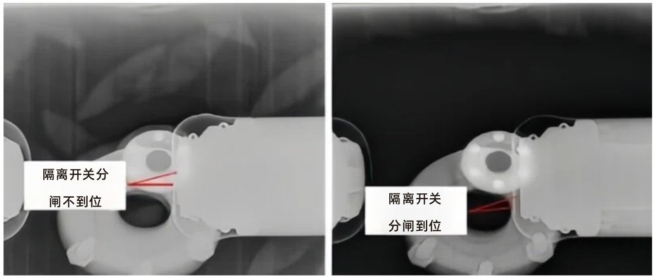
Abnormal movement Whether the opening and closing of the circuit breaker/isolating switch are in place (such as incomplete insertion of contacts, insufficient travel) Whether the crimping fittings have excessive pressure, leakage pressure, insufficient pressure, etc |
|
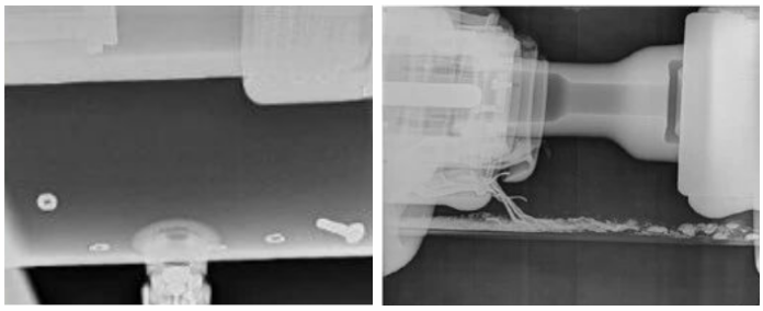
| Foreign matter residue Is there any metal debris, welding slag, or missing tool parts (typical foreign object defects) inside |
Structural damage Are there cracks in the insulation rod/insulator Are there any burn marks on the conductive rod Is the shielding cover displaced Whether there are cracks, missing or broken strands, bends, etc. in the crimping fittings |
|
2.4 GIS Detection Case
 |
|  |
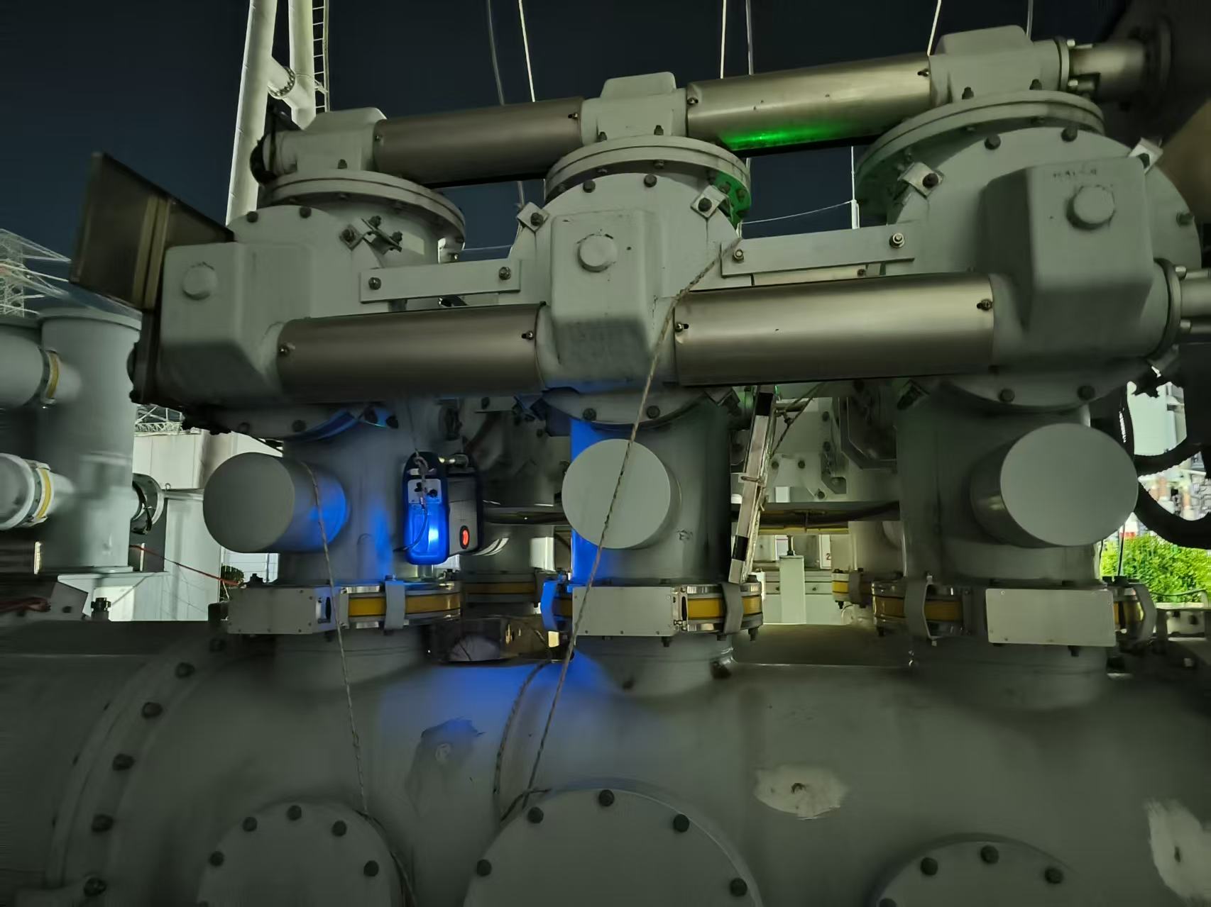
Usage scenario: During the inspection of a GIS substation, problems were found and iStarXM was used for detection | ||
1100kV GIS isolation switch detection A-01 | |
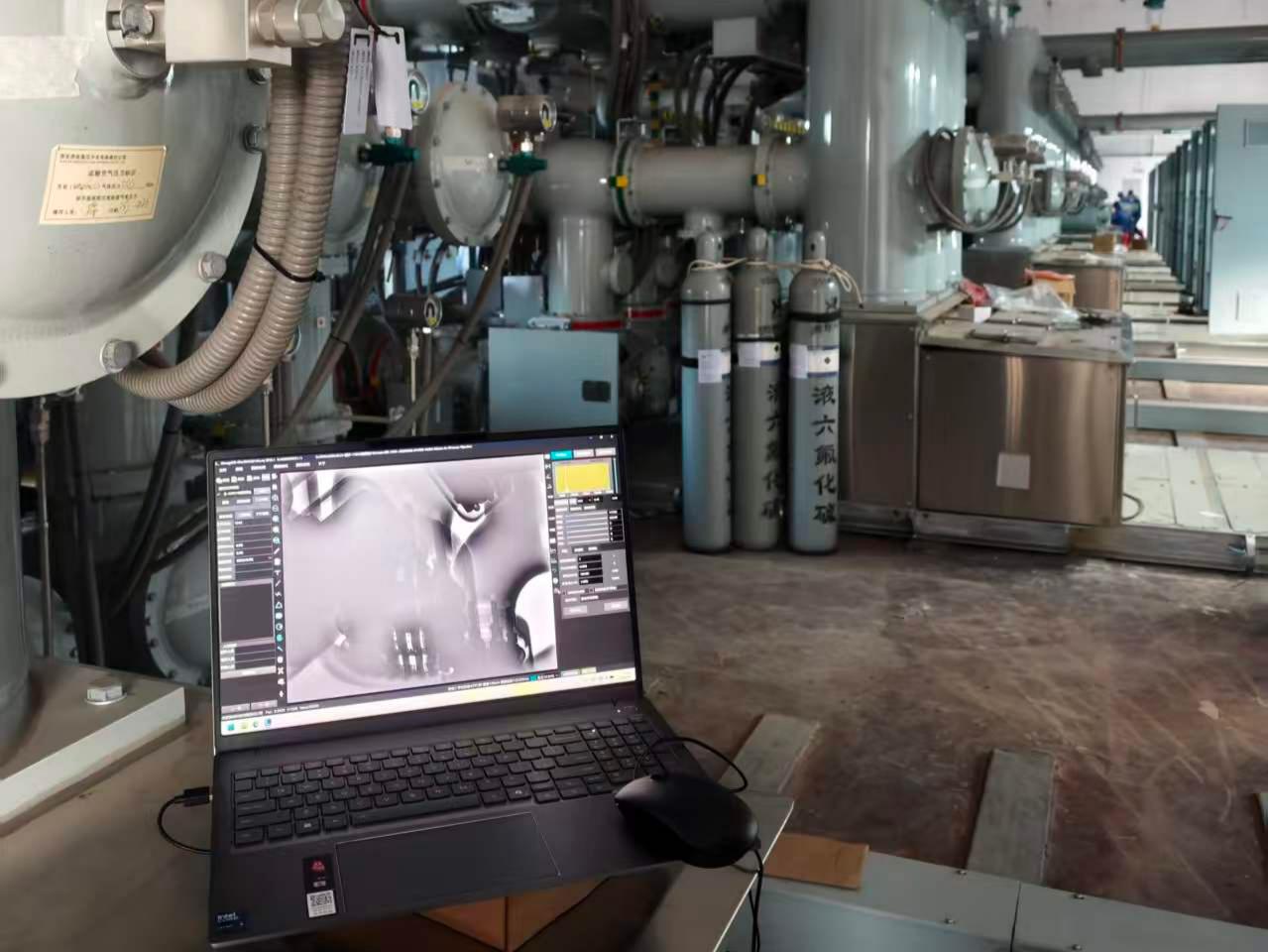
1100kV GIS isolation switch detection A-02 | |
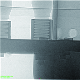
Usage scenario: Vibration was found during the inspection of a GIS substation, and the equipment manufacturer issued a situation report after on-site inspection. Due to the inability of conventional X-ray machines to penetrate this point,iStarLinacX series linear accelerators were used for detection |